Designing a Flexible Printed Circuit (FPC) requires a complete shift in mindset. Unlike rigid boards, an FPC is a mechanical component as much as an electrical one. If you apply standard rigid design rules to a Flex-PCB, the copper will likely crack during its first bend.
At Hansphere, we’ve seen thousands of designs. Here are the essential layout guidelines to ensure your flexible circuits survive millions of flex cycles.
Why Flexible PCB Layout Rules Are Different
In flexible PCBs, layout directly impacts:
- Mechanical fatigue life
- Bend reliability
- Assembly yield
- Long-term electrical stability
Poor layout choices often cause failures after deployment, not during initial testing.

1. The Golden Rule: Respect the Bend Radius
The most common cause of FPC failure is over-stressing the copper in the bend area.
Pro Tip: Never place vias, pads, or components in or near the bend area. These create “stiffness points” that concentrate stress and lead to immediate fractures.
Static Applications: The bend radius should be at least 6x to 10x the total thickness of the flex cable.
Dynamic Applications: For continuous flexing (like a printer head), the radius must be at least 20x the thickness.
2. Advanced Routing Tactics for Flexibility
Staggered Traces (The Anti-I-Beam Effect)
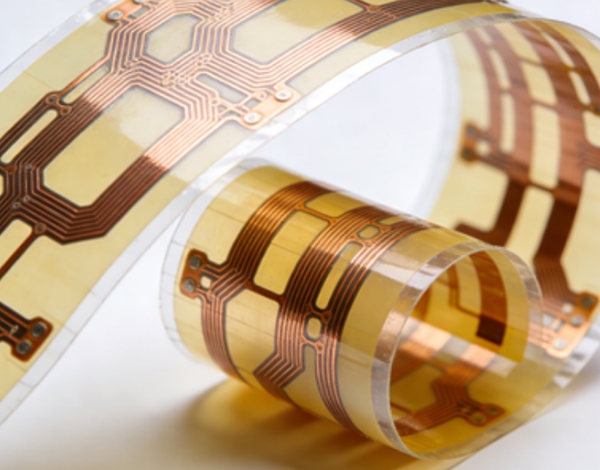
In double-sided flex designs, if traces on the top and bottom layers are stacked directly on top of each other, they create an “I-Beam” effect, making the board stiff and prone to cracking.
- The Fix: Offset (stagger) the traces so that a top-layer trace sits between two bottom-layer traces. This distributes the tension evenly during bending.
Curved Traces vs. 45-Degree Bends
While 45-degree angles are standard for Rigid PCBs, they are stress concentrators in flex designs.
- Guideline: Use true radiused (curved) traces for all corners in the flex area. This allows the copper to expand and contract smoothly without creating a focal point for a crack.
Teardrops and Anchors
Flex pads are prone to “peeling” off the Polyimide base because the adhesive bond is weaker than on FR-4.
- Implementation: Always use Teardrops at the junction of every pad and trace. Additionally, use “Anchor Spurs” (extra copper tabs extending under the coverlay) for large connector pads to provide mechanical reinforcement.
5 Steps to a “Flex-Aware” Layout
Target: PCB Designers & Product Engineers
Goal: Maximizing Flex Life and Manufacturing Yield
- Step 1: Define the Flex Zones & Stiffeners
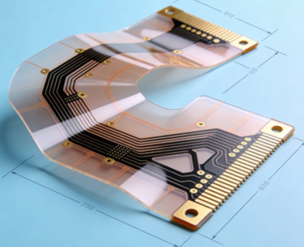
Identify which areas must be flexible and which must stay rigid. Use Rigid-Flex PCB technology if you need to mount heavy components like BGAs on a rigid section while maintaining a flexible interconnect.
- Step 2: Minimize Copper Thickness
Thickness is the enemy of flexibility. Use 1/2 oz (18µm) or even 1/3 oz copper whenever the current requirements allow. Thinner copper has a much higher fatigue life.
- Step 3: Optimize the Ground Plane
A solid copper plane makes a flex board very stiff.
The Solution: Use a Cross-Hatch Pattern for ground planes. This provides the necessary EMI shielding while significantly increasing the board’s suppleness. - Step 4: Coverlay Design vs. Solder Mask
Standard liquid solder mask is brittle and will crack on a flex board.
Requirement: Use Polyimide Coverlay for the flexible sections. Ensure the coverlay “overlap” on the copper traces is at least 0.1mm to prevent chemistry from seeping in during PCB Manufacturing. - Step 5: Termination and Strain Relief
Where the flex cable exits a stiffener or a connector, add a “Strain Relief” (often a bead of epoxy or an extra layer of PI) to prevent the cable from kinking at the transition point.
3. Common Pitfalls to Avoid
Ignoring the Grain Direction: Copper foil has a “grain” from the rolling process. Align your primary bends perpendicular to the grain direction for maximum durability.
Plated Through-Holes (PTH) in Flex Areas: Never do this. The plating is rigid and will crack. Keep all vias in the stiffened areas.
Abrupt Outline Changes: Avoid sharp “V” cutouts in the board outline. Use a radiused “U” shape to prevent the edge from tearing.
FAQ – Flexible PCB Layout Design
A: No. Flex PCBs require routing rules optimized for bending and mechanical stress.
A: This orientation minimizes strain on copper during bending.
A: No, but they should be avoided in dynamic bend areas.
A: Only carefully. Large pours reduce flexibility and may cause stress concentration.
A: Only in static flex areas with sufficient mechanical support.
A: At the layout planning stage—waiting until routing is complete is too late.
A: It is possible but not recommended for high-reliability applications unless you use a Stiffener (FR-4 or PI) directly behind the component to prevent the solder joints from cracking.
A: ENIG (Electroless Nickel Immersion Gold) is usually preferred because it is flat and provides excellent solderability for PCB Assembly, though for extreme flexing, immersion silver or OSP may be used to avoid “nickel embrittlement.”
A: We provide full 3D DRC checks to ensure that your folded design doesn’t have mechanical interference. Our About Us page details our specialized LDI and lamination equipment for multi-layer flex production.
Conclusion
A successful Flexible PCB layout is a marriage of electrical integrity and mechanical endurance. By following these “flex-first” rules—staggering traces, using cross-hatching, and respecting bend radii—you can create a product that is both thin and incredibly robust.
Need a Professional Design Review? Designing for flex is tricky. Hansphere’s Engineering Team offers a comprehensive DFM review for every PCB Design project to ensure your board won’t fail in the field. Get a Quote Today.