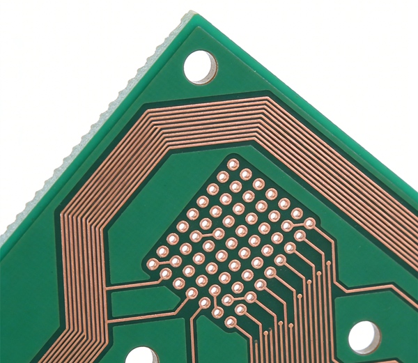
PCB material selection plays a critical role in high-frequency circuit performance. While FR4 remains the most widely used PCB substrate in the electronics industry, it is not always the best choice for RF and microwave applications.
High-frequency circuits require materials with stable dielectric properties and low signal loss. In many of these cases, designers choose Rogers PCB materials instead of standard FR4 laminates.
Understanding the differences between these materials helps engineers select the most appropriate substrate for their designs.
For an overview of FR4 properties, see FR4 PCB Material Guide: Properties, Advantages, and Applications.
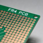
What Is FR4 PCB Material?
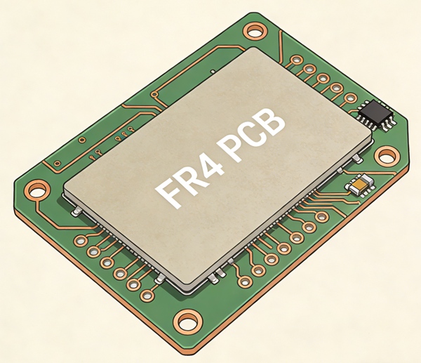
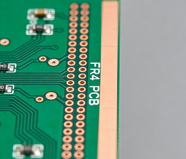
FR4 is a fiberglass-reinforced epoxy laminate widely used in PCB manufacturing. It offers good electrical insulation, mechanical strength, and relatively low production cost.
Because of these advantages, FR4 is commonly used in:
- consumer electronics
- industrial equipment
- computing hardware
- communication devices
However, FR4 materials typically have higher dielectric loss at high frequencies, which can affect signal integrity in RF circuits.
More details about FR4 structure and performance are explained in FR4 PCB Stackup Design Guide.
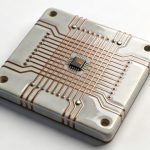
What Is Rogers PCB Material?
Rogers PCB materials are engineered laminates designed specifically for high-frequency and RF applications.
Unlike FR4 laminates, Rogers substrates use specialized hydrocarbon ceramic or PTFE-based materials that provide stable electrical characteristics across a wide frequency range.
Common Rogers material families include:
- Rogers RO4000 series
- Rogers RO3000 series
- Rogers RT/duroid materials
These laminates are widely used in RF communication systems, microwave electronics, and radar applications.
Electrical Performance Comparison
The main difference between FR4 and Rogers materials lies in their dielectric properties and signal loss.
| Property | FR4 | Rogers |
|---|---|---|
| Dielectric constant stability | moderate | very stable |
| Dielectric loss | higher | lower |
| Frequency performance | moderate | excellent |
| Thermal stability | standard | improved |
| Material cost | low | higher |
Because Rogers laminates maintain more stable dielectric characteristics across frequency ranges, they are better suited for RF and microwave circuits.
Design techniques for high-frequency circuits are discussed further in High-Speed PCB Design Guide.
Signal Loss in High-Frequency Circuits
As signal frequency increases, dielectric loss becomes a more important factor in PCB material selection.
FR4 materials can introduce greater signal attenuation at higher frequencies due to their relatively high loss tangent.
Rogers laminates are engineered with lower loss characteristics, which helps preserve signal integrity in high-frequency designs.
This difference becomes especially important in applications such as:
- RF amplifiers
- microwave circuits
- high-speed communication systems
Cost and Manufacturing Considerations
While Rogers materials offer superior electrical performance, they are typically more expensive than FR4 laminates.
Additional manufacturing considerations may include:
- specialized lamination processes
- controlled impedance requirements
- hybrid stackup designs
In some cases, designers combine FR4 and Rogers materials in a hybrid PCB stackup to balance performance and cost.
Manufacturing considerations for multilayer boards are explained in PCB Manufacturing Process Step by Step.
How to Choose Between FR4 and Rogers PCB Materials
Selecting the right PCB substrate for high-frequency circuits requires evaluating several design factors.
- 1. Determine the Operating Frequency
The first step is understanding the frequency range of the circuit.
FR4 materials can perform adequately in many digital circuits and lower-frequency RF applications. However, as frequency increases, signal loss may become more significant. - 2. Evaluate Signal Integrity Requirements
High-speed or RF circuits often require stable impedance and minimal signal attenuation.
Rogers materials provide lower dielectric loss, which helps maintain signal quality across longer trace lengths. - 3. Consider Thermal and Environmental Conditions
Some RF systems operate in demanding environments such as outdoor communication infrastructure or aerospace equipment.
In these cases, the improved thermal stability of Rogers laminates may be beneficial.
Thermal considerations for PCB design are discussed in Thermal Management in PCB Design. - 4. Compare Cost Constraints
FR4 materials are significantly less expensive and widely available.
For designs where performance requirements allow it, FR4 remains the most economical choice.
However, when signal integrity is critical, Rogers materials may justify the higher cost.
Manufacturing cost factors are explained further in PCB Manufacturing Cost Factors.
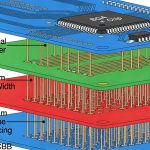
Hybrid FR4 and Rogers PCB Designs
In many modern electronic systems, engineers use hybrid PCB structures that combine FR4 and Rogers materials within the same board.
Typical hybrid designs may include:
- Rogers layers for RF signal routing
- FR4 layers for power and digital circuits
This approach allows designers to achieve high-frequency performance while controlling overall manufacturing cost.
Conclusion
FR4 remains the most widely used PCB substrate due to its cost efficiency and reliable performance in many electronic applications.
However, for high-frequency circuits where signal integrity and low loss are critical, Rogers materials provide significant advantages.
Selecting between FR4 and Rogers laminates depends on operating frequency, signal integrity requirements, environmental conditions, and cost considerations.
FAQ
A: Rogers materials have lower dielectric loss and more stable dielectric constants, which helps maintain signal integrity in RF and microwave circuits.
A: FR4 can be used for lower-frequency RF circuits, but higher frequencies may require specialized materials with lower loss characteristics.
A: Yes. Rogers laminates generally cost more than FR4 materials due to their specialized material composition and manufacturing requirements.
A: A hybrid PCB combines Rogers layers for RF signals with FR4 layers for digital and power circuits, balancing performance and cost.
A: Rogers materials are typically chosen for high-frequency circuits where signal loss, impedance stability, and RF performance are critical.