Once you move into high-speed or RF design, insertion loss stops being a theory problem and starts showing up in measurements.
You route a trace, simulate it, and everything looks fine. Then the real board comes back, and the signal amplitude is lower than expected. That drop is insertion loss.
At a basic level, insertion loss is just how much signal you lose from one end of a trace to the other. In PCBs, most of it comes from two places:
- dielectric loss (material)
- conductor loss (copper)
Understanding both helps you know where the problem is—and what you can realistically fix.
For material background, see FR4 Dielectric Constant (Er) vs Frequency Explained.

What Is Insertion Loss?
Insertion loss is usually expressed in dB and represents signal attenuation through a transmission path.
Higher loss → weaker signal at the receiver.
It depends on:
- trace length
- frequency
- material properties
- copper surface condition
Loss increases with frequency, which is why it becomes critical in:
- high-speed digital links
- RF circuits
- long backplane traces
Dielectric Loss
Dielectric loss comes from the PCB substrate itself.
As the signal propagates, part of the electromagnetic energy is absorbed by the dielectric material and converted into heat.
This is mainly controlled by:
- loss tangent (Df)
- frequency
- dielectric constant behavior
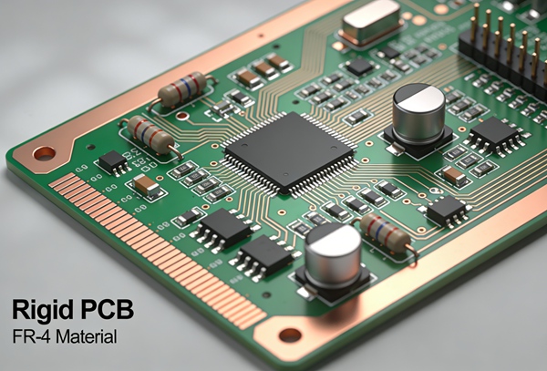
FR4 has a relatively higher loss tangent compared to RF materials, which is why it performs worse at higher frequencies.
This is covered in more detail in Low-Loss PCB Materials for RF and Microwave Circuits.
Conductor Loss
Conductor loss is related to the copper trace.
At higher frequencies, current does not flow uniformly through the entire conductor. Instead, it concentrates near the surface—a phenomenon known as the skin effect.
As frequency increases:
- effective resistance increases
- signal attenuation increases
Surface roughness also plays a role. Rough copper increases the effective path length of current, which increases loss.
Dielectric vs Conductor Loss (Quick Comparison)
| Loss Type | Source | Dominant At | Key Factors |
|---|---|---|---|
| Dielectric Loss | PCB material | higher frequencies | loss tangent, Er |
| Conductor Loss | copper traces | all frequencies (worse at high freq) | skin effect, roughness |
In most RF designs:
- dielectric loss dominates at very high frequencies
- conductor loss is always present and can’t be ignored
How Frequency Affects Insertion Loss
Insertion loss increases roughly with frequency.
- dielectric loss increases almost linearly with frequency
- conductor loss increases with the square root of frequency
That’s why a design that works fine at 1 GHz may struggle at 10 GHz without any geometry change.
How to Reduce PCB Insertion Loss
You can’t eliminate loss—but you can manage it.
- 1. Choose Lower-Loss Materials
This is usually the biggest lever.
switch from FR4 → low-loss FR4 → Rogers → PTFE
lower loss tangent = less dielectric loss
See FR4 vs Rogers PCB for High-Frequency Design - 2. Shorten Critical Signal Paths
Loss is proportional to length.
Simple but often overlooked:
place components closer
reduce unnecessary routing - 3. Optimize Stackup
Stackup affects both loss and impedance.
keep signals close to reference planes
control dielectric thickness
avoid unnecessary layer transitions
Details: FR4 PCB Stackup Design Guide - 4. Use Smoother Copper
Copper roughness increases conductor loss.
Many high-speed designs use:
low-profile copper
very-low-profile (VLP) copper - 5. Control Trace Geometry
Wider traces → lower resistance → lower conductor loss
But this must be balanced with impedance requirements.
How to Estimate Insertion Loss in PCB Design
In practice, engineers don’t calculate everything manually.
1. Use Field Solvers or Simulation Tools
Tools can model:
- dielectric loss
- conductor loss
- frequency-dependent behavior
2. Use Manufacturer Data
Laminate suppliers provide:
- loss tangent vs frequency
- dielectric constant curves
These are more reliable than generic assumptions.
3. Validate with Measurement
For critical designs:
- TDR (time-domain reflectometry)
- VNA (vector network analyzer)
Measured data often reveals things simulation misses.
Practical Design Observations
Some patterns show up repeatedly:
- switching material has more impact than tweaking trace width
- loss becomes visible faster than expected as frequency increases
- simulation accuracy depends heavily on material models
- ignoring copper roughness leads to optimistic results
Conclusion
Insertion loss in PCBs mainly comes from dielectric loss and conductor loss.
FR4 works well for many designs, but as frequency increases, both types of loss become more significant. Material choice, stackup design, and trace geometry all play a role in managing signal attenuation.
The goal isn’t zero loss—it’s predictable loss that stays within your system margin.
FAQ
Insertion loss is the reduction in signal strength as it travels through a PCB trace, usually measured in dB.
The main causes are dielectric loss (material absorption) and conductor loss (copper resistance and skin effect).
At high frequencies, dielectric loss often dominates, but conductor loss is always present.
No. It can only be reduced and managed through design and material selection.
Using tools like vector network analyzers (VNA) and time-domain reflectometry (TDR).