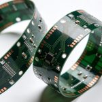
Rigid-flex PCB performance and reliability depend heavily on stackup architecture and material selection. The combination of rigid and flexible layers requires careful engineering to ensure mechanical durability, electrical stability, and manufacturability.
This article explains rigid-flex PCB stackup and material selection, including layer structures, materials, and key design considerations.
🔗 Part of the Rigid-Flex PCB Design Series
Rigid-Flex PCB Design: Fundamentals, Materials, Manufacturing, and Reliability
Why Stackup Design Is Critical in Rigid-Flex PCBs
Unlike standard rigid boards, rigid-flex designs must address:
- Mechanical bending stress
- Layer transition reliability
- Adhesion between rigid and flex sections
A well-designed stackup prevents cracking, delamination, and electrical failure.
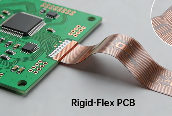
Typical Rigid-Flex PCB Stackup Structure
A common rigid-flex stackup includes:
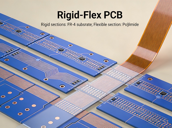
- Rigid FR-4 cores
- Flexible polyimide layers
- Bonding layers or adhesive systems
- Copper signal layers
- Coverlay for flex protection
The flex region is engineered with thinner dielectrics to enable bending.
Single-Sided vs Multilayer Flex Sections
Single-Layer Flex
- Higher flexibility
- Lower cost
- Limited routing density
Multilayer Flex
- Higher circuit density
- Better shielding
- Increased complexity
Choice depends on performance requirements.
Key Stackup Design Principles
Neutral Bend Axis Control
Place copper layers symmetrically around the neutral axis to minimize stress during bending.
Layer Symmetry
Balanced structures prevent warpage and mechanical failure.
Controlled Impedance Planning
Stackup must support impedance targets before routing begins.
Material Selection for Rigid Sections
Common materials include:
- Standard FR-4
- High-Tg FR-4
- Low-loss laminates for high-speed signals
Rigid materials provide structural stability and component support.
Material Selection for Flex Sections
Flex regions typically use:
- Polyimide substrates
- Rolled annealed copper (RA copper)
- Adhesive or adhesiveless laminates
These materials improve bending durability.
Adhesive vs Adhesiveless Constructions
Adhesive-Based
- Lower cost
- Slightly reduced reliability
Adhesiveless
- Better thermal performance
- Higher reliability
Used in high-end applications.
Coverlay vs Solder Mask
Flex sections use coverlay instead of solder mask because:
- It withstands repeated bending
- Provides better insulation
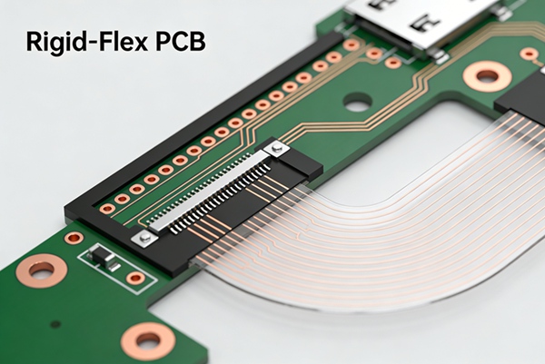
Transition Zone Design
The rigid-to-flex transition area must:
- Avoid abrupt thickness changes
- Use gradual reinforcement
- Minimize stress concentration
This area is a common failure point.
Manufacturability Considerations
To improve fabrication success:
- Use standard material systems
- Limit excessive layer counts
- Validate stackup with the manufacturer
Early collaboration reduces redesign risk.
Common Stackup Mistakes
- Copper imbalance
- Incorrect bend radius assumptions
- Poor transition design
These issues often cause early product failures.
Best Practices Summary
- Design stackup around mechanical requirements
- Use RA copper for dynamic flex
- Maintain symmetry
- Define impedance early
- Validate with fabrication partners
Conclusion
Rigid-flex PCB stackup and material selection define the mechanical durability and electrical performance of the final product. Proper engineering ensures long-term reliability and successful manufacturing.
This article establishes the structural engineering layer of the Rigid-Flex PCB content cluster.
FAQ – Rigid-Flex Stackup and Materials
A: Polyimide is the most common flex substrate.
A: Yes, especially for high-reliability applications.
A: It has better fatigue resistance during bending.
A: Yes, with proper stackup design.
A: The rigid-to-flex transition zone.