Printed circuit boards are available in several structural formats. The most common types are rigid PCBs, flexible PCBs, and rigid-flex PCBs.
Although all three technologies serve the same fundamental purpose—providing electrical interconnection between components—their mechanical structures and design constraints are quite different.
Understanding these differences helps engineers choose the most suitable PCB technology for their product.
Rigid PCB Overview
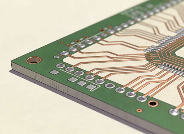
Rigid PCBs are the most widely used circuit boards in electronics.
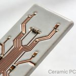
They are built using rigid laminate materials such as FR-4, which provide mechanical stability and strong support for electronic components.
Rigid PCBs cannot bend or flex once manufactured. Because of their stable structure and relatively simple manufacturing process, they are typically the lowest-cost PCB solution.
Typical applications include:
- consumer electronics
- industrial control systems
- computer hardware
- communication equipment
Rigid PCBs are also easier to manufacture in large volumes and support high layer counts for complex designs.
More details about rigid board structures are explained in Rigid PCB Design Guide: Layout, Stackup, and Manufacturing Considerations.
Flexible PCB Overview
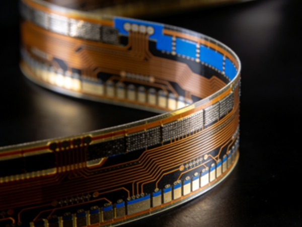
Flexible PCBs, often called flex circuits, are designed to bend or fold during installation or operation.
Instead of rigid laminates, flex circuits use thin polyimide substrates that allow the circuit to conform to different shapes.
Because flex circuits eliminate the need for connectors and wiring harnesses, they are widely used in compact electronic products.
Common applications include:
- cameras and mobile devices
- wearable electronics
- medical instruments
- aerospace systems
Flex circuits also reduce system weight and improve reliability by eliminating mechanical connectors.
However, flex PCBs require careful routing and mechanical design to avoid copper fatigue during bending.
For a deeper explanation of flex design rules, see Flexible PCB Design Guide: Materials, Layout, and Reliability.
Rigid-Flex PCB Overview
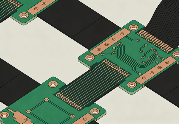
Rigid-flex PCBs combine rigid circuit boards and flexible circuits within a single structure.
Rigid areas support components, while flexible sections allow the board to bend or fold between different mechanical sections of the product.
This design approach eliminates connectors and cables between rigid boards, improving reliability and reducing assembly complexity.
Rigid-flex PCBs are commonly used in high-reliability applications such as:
- aerospace electronics
- medical equipment
- military systems
- compact consumer devices
Because rigid and flexible materials must be laminated together, rigid-flex PCBs are more complex to manufacture than either rigid or flex circuits alone.
A detailed introduction to this technology can be found in Rigid-Flex PCB Design: Fundamentals and Applications.
Structural Differences
The fundamental difference between the three PCB types lies in their mechanical structure.
Rigid PCBs use thick fiberglass laminates that provide structural support.
Flex circuits use thin polyimide substrates that allow repeated bending.
Rigid-flex boards integrate both structures into a single board, allowing rigid component areas connected by flexible interconnects.
This structural difference directly affects how the boards are designed and manufactured.
Design Considerations
Each PCB type requires different design considerations.
Rigid PCB design focuses on signal integrity, layer stackup, and component placement. Mechanical flexibility is not a concern.
Flex PCB design must account for bend radius, copper fatigue, and routing direction relative to the bending axis.
Rigid-flex PCB design combines both sets of requirements. Designers must manage mechanical stress in flex areas while maintaining reliable rigid sections for component mounting.
Proper stackup planning is especially important in rigid-flex boards.
More details are discussed in Rigid-Flex PCB Stackup Design Guide.
Reliability and Mechanical Performance
Reliability characteristics also differ between the three PCB types.
Rigid PCBs provide strong mechanical support but cannot accommodate movement within the product structure.
Flex circuits can withstand bending but require careful design to prevent copper fatigue.
Rigid-flex PCBs often offer the best reliability in complex systems because they eliminate connectors and reduce mechanical interconnects.
However, reliability depends heavily on proper flex region design and bend radius control.
These considerations are explained in Rigid-Flex PCB Bend Radius and Reliability Design Rules.
Manufacturing Complexity
Manufacturing difficulty increases from rigid PCBs to flex circuits and rigid-flex boards.
Rigid PCBs are produced using well-established multilayer fabrication processes.
Flex circuits require specialized materials and handling procedures due to the thin polyimide substrates.
Rigid-flex PCBs combine both processes and often require multiple lamination cycles, making them the most complex and expensive option.
A detailed explanation of production considerations can be found in Rigid-Flex PCB Manufacturing Process and Design Guidelines.
Cost Considerations
Cost differences between the three PCB types are largely related to materials and manufacturing complexity.
Rigid PCBs generally offer the lowest cost for high-volume products.
Flex circuits cost more due to polyimide materials and specialized fabrication processes.
Rigid-flex PCBs typically have the highest fabrication cost. However, they can reduce overall system cost by eliminating connectors, cables, and assembly steps.
In many compact electronic products, these system-level savings justify the higher PCB fabrication cost.
Typical Applications
Each PCB type is best suited for different product requirements.
Rigid PCBs are commonly used in desktop electronics, industrial equipment, and standard consumer products.
Flex circuits are widely used in devices requiring compact packaging and lightweight structures.
Rigid-flex boards are preferred when both mechanical flexibility and high reliability are required within the same product.
Selecting the appropriate PCB technology depends on electrical requirements, mechanical constraints, and manufacturing considerations.
Conclusion
Rigid PCBs, flex circuits, and rigid-flex boards each offer unique advantages.
Rigid PCBs provide stability and cost efficiency. Flex circuits enable compact and lightweight designs. Rigid-flex PCBs combine the strengths of both technologies, allowing complex mechanical integration in advanced electronic systems.
Understanding the differences between these technologies helps engineers select the most appropriate solution for their product design.
FAQ
A: Rigid PCBs use solid laminate materials and cannot bend, while flex PCBs use thin polyimide substrates that allow the circuit to bend or fold.
A: Rigid-flex PCBs are typically used when electronic systems require both rigid component mounting areas and flexible interconnections within the same board.
A: In many applications, rigid-flex PCBs improve reliability because they eliminate connectors and cables that can loosen or fail over time.
A: These boards use specialized materials such as polyimide substrates and require more complex manufacturing processes compared with standard rigid PCBs.
A: Flex circuits and rigid-flex PCBs are often preferred for compact electronics because they allow the circuit to fold or conform to tight mechanical spaces.