At some point in high-speed design, “rough routing” stops working.
You start seeing:
- reflections
- signal distortion
- unstable links
That’s when impedance control becomes necessary.
Most designs target:
- 50Ω (single-ended)
- 100Ω differential (paired signals)
Getting there is not just about trace width—it’s a combination of stackup, materials, and manufacturing tolerances.
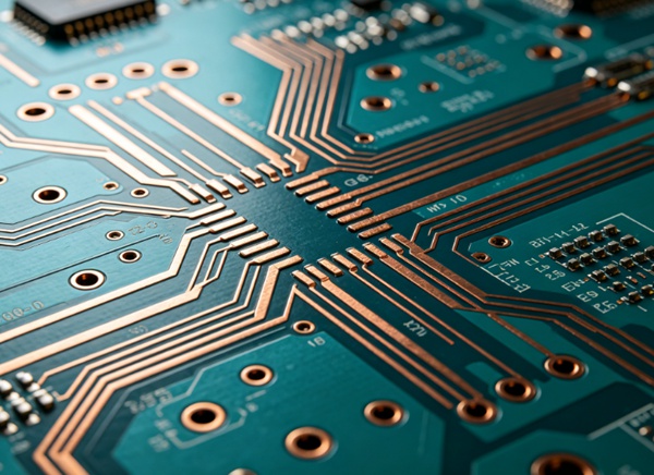
What Is Controlled Impedance?
Controlled impedance means designing PCB traces so that their characteristic impedance stays within a specified tolerance (for example, 50Ω ±10%).
It depends on:
- trace width
- trace thickness
- dielectric thickness
- dielectric constant (Er)
- reference plane
If any of these change, impedance changes.
Background on Er: FR4 Dielectric Constant (Er) vs Frequency Explained
Why 50Ω and 100Ω?
These values are not random.
- 50Ω is a common standard for single-ended RF and high-speed signals
- 100Ω differential is widely used for interfaces like LVDS, USB, Ethernet
They represent a balance between:
- signal loss
- power handling
- manufacturability
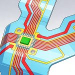
Common Transmission Line Structures
Impedance depends heavily on stackup.
Microstrip (Outer Layer)
- trace on outer layer
- reference plane below
Pros:
- easy to route
- accessible
Cons:
- more EMI
- more sensitive to environment
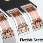
Stripline (Inner Layer)
- trace between two reference planes
Pros:
- better shielding
- lower EMI
- more stable impedance
Cons:
- harder to access
- tighter fabrication control
Stackup basics: FR4 PCB Stackup Design Guide
Key Factors That Affect Impedance
1. Trace Width
Wider trace → lower impedance
Narrower trace → higher impedance
2. Dielectric Thickness
Greater distance to plane → higher impedance
3. Dielectric Constant (Er)
Higher Er → lower impedance
4. Copper Thickness
Thicker copper slightly lowers impedance
5. Reference Plane Quality
A continuous plane is required for stable impedance.
Return path details: PCB Return Path and Ground Plane in High-Speed Design
50Ω vs 100Ω Differential (Quick Comparison)
| Parameter | 50Ω Single-Ended | 100Ω Differential |
|---|---|---|
| Signal type | single line | paired lines |
| sensitivity | moderate | higher |
| routing complexity | lower | higher |
| noise immunity | lower | higher |
Differential pairs rely on tight coupling between the two traces.
How to Achieve Controlled Impedance
This is where designs succeed or fail.
- 1. Start with Stackup (Not Routing)
Define:
.layer structure
.dielectric thickness
.material type
.before routing anything.
If the stackup is wrong, trace tuning won’t fix it. - 2. Use Impedance Calculators or Field Solvers
Tools estimate trace geometry based on:
.target impedance
.material properties
But remember: tools are approximations. - 3. Work with Your PCB Manufacturer Early
This step is often skipped—and causes problems later.
Manufacturers provide:
.actual laminate data
.achievable tolerances
.impedance tables
They can adjust stackup to hit your target. - 4. Control Differential Pair Geometry
For 100Ω differential:
. spacing between traces matters as much as width
. tighter spacing → lower differential impedance
Also keep:
. equal length
. consistent spacing
. minimal skew
Crosstalk considerations: PCB Crosstalk Explained (Near-End vs Far-End Crosstalk - 5. Maintain Continuous Reference Planes
Avoid:
. plane splits
. routing across voids
These break impedance continuity. - 6. Account for Manufacturing Tolerances
Real boards vary.
Typical tolerance:
. ±5% to ±10% impedance
So design margins accordingly.
Common Mistakes
These show up frequently:
- defining impedance after routing
- ignoring prepreg variation
- relying only on generic Er values
- not confirming with manufacturer
- breaking return paths with vias or splits
How to Verify Impedance
You don’t just “trust the design”.
1. Simulation
Field solvers estimate impedance and loss.
2. Fabrication Test Coupons
Manufacturers include impedance test structures on the panel.
3. Measurement
- TDR (time-domain reflectometry)
- impedance measurement tools
These confirm actual results.
Practical Design Notes
From real projects:
- stackup decisions matter more than trace tweaks
- inner layers are more stable than outer layers
- small spacing errors can break differential impedance
- communication with the PCB fab saves time
Conclusion
Controlled impedance design is a combination of geometry, materials, and manufacturing control.
50Ω and 100Ω targets are achievable, but only when stackup, routing, and fabrication are aligned. The earlier impedance is considered in the design process, the easier it is to meet performance requirements.
FAQ
A: It means designing traces to maintain a specific impedance value within tolerance.
A: It provides a balance between signal integrity and manufacturability for many applications.
A: Because two coupled traces combine to create a standard differential impedance used in many interfaces.
A: Not easily. It usually requires stackup or geometry changes.
A: Typically within ±5% to ±10%, depending on manufacturing capability.