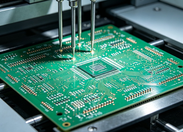
A PCB can pass electrical testing and still fail in the real world.
No shorts.
No opens.
All components correctly installed.
And yet:
the product still doesn’t work.
That’s where functional testing (FCT) comes in.
Unlike ICT or flying probe testing, functional testing checks:
“Does the assembled PCB actually perform as intended?”
For many products, this is the final checkpoint before shipment.
What Is Functional Testing (FCT)?
Functional testing verifies PCB operation under real or simulated conditions.
Instead of checking isolated circuits, it evaluates:
- system behavior
- signal performance
- communication
- power-up sequence
In simple terms:
ICT checks if the board is built correctly.
FCT checks if the board actually works.
Why Electrical Testing Is Not Enough
Electrical tests are good at finding:
- shorts
- opens
- wrong component values
But they often miss:
- firmware problems
- timing issues
- unstable communication
- sensor failures
- interface errors
A board can be electrically correct and still fail functionally.
What Functional Testing Typically Verifies
The exact process depends on product type.
Typical checks include:
Power-On Verification
Can the board start normally?
Checks:
- startup sequence
- power rails
- boot stability
Communication Interfaces
Verify protocols such as:
- UART
- USB
- Ethernet
- CAN bus
- SPI / I2C
Communication failure is a common issue.
Signal Measurement
Test whether signals behave correctly.
Examples:
- clock frequency
- voltage level
- waveform integrity
Related: Controlled Impedance PCB Design: How to Achieve 50Ω and 100Ω
Sensor and Peripheral Function
Products with:
- displays
- motors
- sensors
- RF modules
often require interaction testing.
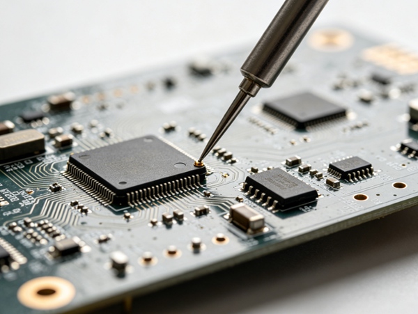
Firmware Validation
In embedded systems:
- firmware upload
- programming verification
- boot behavior
may be part of FCT.
Functional Testing vs ICT vs Flying Probe
| Feature | ICT | Flying Probe | Functional Test |
|---|---|---|---|
| opens/shorts | yes | yes | partial |
| component verification | yes | yes | limited |
| real operation | no | no | yes |
| firmware testing | no | no | yes |
| communication testing | no | limited | yes |
These methods are complementary.
Not competitive.
Overview: ICT vs Flying Probe Testing: Which PCB Test Is Better?
Types of Functional Testing
Manual Functional Testing
Operator performs:
- visual confirmation
- button testing
- basic verification
Best for:
- prototypes
- low volume
Automated Functional Testing
Uses dedicated fixtures and software.
Advantages:
- repeatability
- faster throughput
- lower operator error
Preferred for:
- production environments
Environmental Functional Testing
The PCB runs under conditions such as:
- temperature variation
- vibration
- long operation time
Often used for:
- automotive
- aerospace
- industrial electronics
When Is Functional Testing Necessary?
Not every PCB requires it.
Usually recommended for:
Smart / Embedded Products
Products with:
- MCU
- firmware
- software interaction
Communication Devices
Products using:
- wireless modules
- network communication
Safety-Critical Systems
Including:
- automotive
- medical
- industrial controls
High-Value Products
When failure cost is high:
additional testing becomes worthwhile.
How to Design a PCB for Better Functional Testing
Testing should be considered during design.
- 1. Add Debug Interfaces
Include access to:
. UART
. JTAG
programming headers - 2. Plan Test Modes Early
Firmware should support:
. diagnostic mode
. self-test mode - 3. Include Test Points
Helps with signal measurement.
- 4. Design Custom Fixtures if Needed
For production:
. pogo-pin fixtures
. automatic interfaces
can improve efficiency.
Common Functional Testing Mistakes
Typical problems:
- skipping firmware validation
- relying only on ICT
- testing too late in development
- poor fixture design
- no failure logging system
Functional testing works best when planned early.
Practical Notes from Real Production
What usually happens:
- prototypes rely on manual functional testing
- production shifts toward automated fixtures
- communication failures are common FCT findings
- firmware-related issues often survive electrical testing
Many “random field failures” are actually functional problems missed during production.
Conclusion
Functional testing fills the gap between electrical verification and real-world operation.
While ICT and flying probe testing ensure electrical correctness, FCT confirms that the PCB actually performs as intended. For products with firmware, communication, or complex functionality, functional testing is often essential for reliability and quality control.
FAQ
A: It verifies whether the assembled PCB actually works under real operating conditions.
A: ICT checks electrical correctness, while functional testing checks system operation.
A: No, but it is strongly recommended for embedded, communication, and high-reliability products.
A: Yes. Firmware or communication issues may still exist.
A: Usually after assembly and electrical testing, before shipment.