It’s possible to get signal routing “right” and still have a board that behaves unpredictably.
Random resets, jitter, noise spikes—often these are not signal problems.
They’re power problems.
High-speed devices draw fast, transient currents. If the power delivery network (PDN) can’t respond quickly, voltage drops and noise show up immediately.
That’s where power integrity design comes in.
What Is Power Integrity (PI)?
Power integrity is about delivering stable voltage to every component under dynamic load conditions.
In practice, this means:
- minimizing voltage ripple
- controlling noise
- ensuring fast current delivery
A good PDN behaves like a low-impedance path across a wide frequency range.
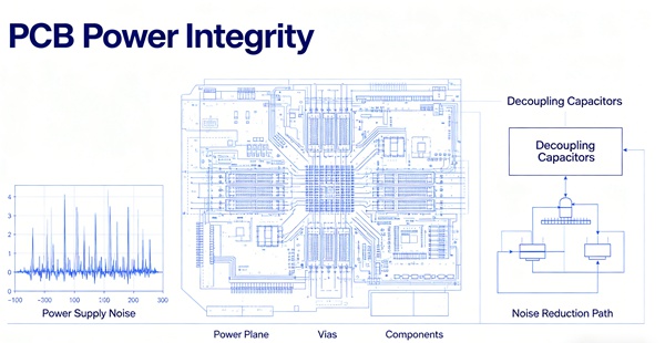
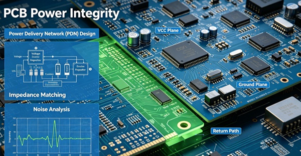
What Is PDN (Power Delivery Network)?
The PDN includes:
- power planes
- ground planes
- decoupling capacitors
- vias and connections
Everything between the power source and the IC pins is part of the PDN.
And every part of it adds impedance.
Why Power Noise Happens
Noise is mainly caused by:
- fast switching currents
- inductance in the power path
- insufficient decoupling
As edge rates increase, current demand becomes more transient.
If the PDN impedance is too high, voltage droops occur.
Decoupling Capacitors (What They Actually Do)
Decoupling capacitors act as local energy storage.
Instead of pulling current from far away, the IC draws from nearby capacitors.
They help:
- stabilize voltage
- reduce noise
- support fast current demand
But they only work well if placed correctly.
Bulk vs High-Frequency Decoupling
You typically need a mix:
| Type | Function | Placement |
|---|---|---|
| Bulk capacitors | low-frequency energy | near power entry |
| Mid-frequency caps | general decoupling | around IC |
| High-frequency caps | fast transients | very close to pins |
No single capacitor works across all frequencies.
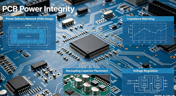
PDN Impedance (Why It Matters)
The goal is simple:
keep PDN impedance as low as possible across the operating frequency range
If impedance spikes:
- voltage drops increase
- noise increases
- system stability decreases
How to Design Good Power Integrity
This is where most real improvements happen.
- 1. Use Solid Power and Ground Planes
Planes provide:
. low impedance
. wide current paths
.better high-frequency behavior
Avoid narrow power traces when possible. - 2. Place Decoupling Capacitors Close to IC Pins
Distance matters.
Longer path = higher inductance = worse performance
Best practice:
. place caps as close as possible
. connect directly to planes - 3. Minimize Loop Inductance
The loop formed by:
power → capacitor → ground
should be as small as possible.
This is similar to return path control.
See: PCB Return Path and Ground Plane in High-Speed Design - 4. Use Multiple Capacitor Values
Different values cover different frequency ranges.
Example:
. 10µF (bulk)
. 1µF
. 0.1µF
. 0.01µF
This creates a wider effective frequency response. - 5. Add Enough Ground Vias
Each capacitor should have:
. a short path to ground
. preferably multiple vias
This reduces inductance.
Power Planes vs Traces
Planes are almost always better for high-speed designs.
Advantages:
- lower impedance
- better current distribution
- improved noise performance
Traces are only suitable for low-current or low-speed cases.
PI and Signal Integrity Connection
Power integrity directly affects signal behavior.
Poor PDN → noisy reference → unstable signals
This can lead to:
- jitter
- timing errors
- increased crosstalk
Related topics:
Stackup and Power Integrity
Stackup design affects PDN performance.
Good practice:
- place power and ground planes close together
- create plane capacitance
- reduce loop inductance
More details: High-Speed PCB Stackup Design (6-Layer vs 8-Layer vs 10-Layer)
Common Mistakes
Typical issues seen in real boards:
- placing capacitors too far from IC pins
- relying on a single capacitor value
- using long thin power traces
- not enough ground vias
- ignoring PDN impedance
How to Evaluate Power Integrity
1. Simulation
PI tools model:
- impedance vs frequency
- voltage ripple
2. Measurement
- oscilloscope (ripple/noise)
- power rail probing
3. Design Review
Check:
- capacitor placement
- plane structure
- via paths
Practical Design Notes
From real designs:
- capacitor placement matters more than quantity
- shorter connections beat larger capacitance
- PDN problems often look like SI problems
- early planning avoids late fixes
Conclusion
Power integrity is essential for stable PCB performance.
A well-designed PDN ensures that high-speed components receive clean, stable power under dynamic conditions. Proper use of planes, decoupling capacitors, and layout techniques can significantly reduce noise and improve overall system reliability.
FAQ
A: It refers to maintaining stable voltage and low noise in the power delivery network.
A: They provide local energy and reduce voltage fluctuations.
A: As close as possible to the IC power pins.
A: It is the resistance to current flow in the power delivery network across frequency.
A: Yes. Poor power quality can introduce noise and degrade signal performance.