Starre PCB
(Multilayer)
From 2-layer prototypes to 32-layer high-speed server boards — the foundation of every electronic system, built to the specification your design actually demands.
The workhorse board technology — built correctly for your application
A rigid multilayer PCB is a stack of copper-clad laminates (cores) and adhesive prepreg layers, pressed together under heat and pressure to form a single rigid board. Through-hole and blind vias connect layers as required by the circuit design.
The word 'standard' is misleading. Material selection, stackup design and fabrication process control vary enormously between suppliers — and these variables directly determine signal performance, thermal reliability and service life.
From standard FR4 for office electronics to high-Tg polyimide for engine bay automotive boards and Rogers laminates for RF designs — the right specification starts with a DFM review that checks the stackup, not just the DRC.
Get Rigid PCB Quote →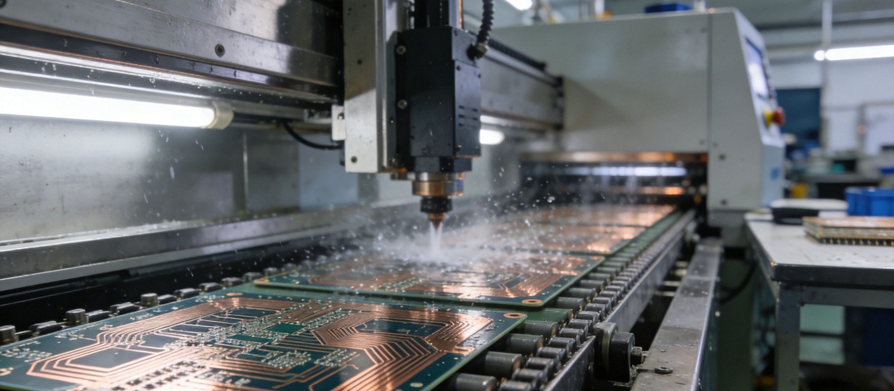
Three specification decisions that determine rigid PCB performance
Two identical schematics built on different stackups will perform differently. These are the variables that matter most.
Stackup Design Controls Impedance — and Impedance Controls Signal Quality
Every high-speed trace on a PCB is a transmission line. Its characteristic impedance is set by trace width, dielectric thickness and laminate Dk — variables that are chosen in the stackup design step, before fabrication begins. A stackup that isn't reviewed against your signal speed targets will produce a board that doesn't perform to simulation, every time.
controlled impedance · Dk vs frequency · TDR verification · ±5% toleranceMaterial Selection for Temperature, Humidity and Chemical Environment
Standard FR4 handles office temperatures and moderate humidity adequately. Automotive engine bay boards at continuous 125°C need high-Tg FR4 (Tg 170–220°C) or polyimide. Outdoor industrial boards exposed to condensation require low-water-absorption laminates. Specifying the wrong base material is the most common root cause of premature PCB failure in the field.
high-Tg FR4 · polyimide · low-water-absorption · halogen-free optionsVia Copper Barrel Thickness Determines Long-Term Reliability
A board that passes electrical test on day one can still fail after 500 thermal cycles if via copper barrel thickness is marginal. IPC-6012 specifies minimum copper thickness in via barrels (18 µm minimum average). Only microsection analysis can confirm this was achieved. We include microsection analysis on every production lot — not as an extra charge, but as a baseline quality requirement.
IPC-6012 via barrel · 18 µm min Cu · microsection QC · thermal cycle lifeFull rigid PCB fabrication specification
All process parameters verified through our ISO 9001 QMS. TDR impedance report supplied with every controlled-impedance order.
Parameter für die Herstellung
| Anzahl der Schichten | 2 – 32 layers |
| Min. Spur/Leerzeichen | 2,5 / 2,5 mil |
| Min. Hole Size | 0.20 mm mechanical · 0.10 mm laser |
| Kupfer Gewicht | 0.5 oz – 20 oz |
| Dicke der Platte | 0.4 mm – 6.4 mm |
Leistung und Standards
| Kontrollierte Impedanz | ±5% TDR verified |
| Laminate Options | FR4 · High-Tg · Polyimide · Rogers · Halogen-free |
| Oberfläche | HASL · ENIG · ENEPIG · OSP · Immersion Ag |
| IPC Build Standard | Class 2 default · Class 3 on request |
| Prototype Turnaround | 48h express · 5 days standard |
How multilayer PCB is manufactured
More process steps than most electronic manufacturing — each one affecting the final board's reliability.
Inner Layer Imaging & Etch
Copper-clad laminate is photolithographically imaged and etched to the final inner-layer circuit pattern. Oxide treatment prepares surfaces for lamination.
Stack-up Press
Inner cores, prepreg and copper foils are precisely aligned and hot-pressed at 175–220°C under 350 psi. Resin flow fills all voids and bonds layers permanently.
Drilling & Desmear
Through-holes are CNC-drilled with carbide bits. Plasma desmear removes epoxy resin from via walls to ensure copper adhesion to inner-layer pads.
Plating, Imaging & Finish
Electroless then electrolytic copper plates via walls to IPC-6012 spec. Outer layer imaging, ENIG/OSP finish and electrical test complete the process.
Where rigid multilayer PCB is the right choice
Standard rigid multilayer is the foundation of virtually every electronic product — the specification is what varies.
Industrial Controllers & PLCs
High-Tg multilayer for PLCs, motion controllers and industrial computers in elevated temperature environments.
Server & Networking
High-layer-count boards for server CPUs, switch ASICs and line cards with DDR5, PCIe 5.0 and 400G Ethernet.
Automotive ECU
High-reliability multilayer for engine control, body control and ADAS processing across the full automotive temperature range.
Medical Instruments
IPC Class 3 multilayer for imaging systems, patient monitors and surgical equipment.
Leistungselektronik
Heavy copper multilayer for motor drives, power converters and UPS systems with high-current bus bars.
Telecom Infrastructure
High-layer backplane and line-card boards for DSLAM, OLT and routing equipment.
Unterhaltungselektronik
Cost-efficient multilayer for smart TVs, set-top boxes and home appliances.
Defense Electronics
Polyimide multilayer for military electronics requiring extended temperature range and IPC Class 3.
Rigid PCB quality — from stackup review to via barrel verification.
Quality on a rigid PCB starts before fabrication. Our DFM review catches stackup and material issues before any copper is etched. Post-fab, 100% e-test and selective microsection confirm via barrel quality on every lot.
- ISO 9001 : 2015Von Dritten geprüftes Qualitätsmanagement
- IPC-6012Rigid PCB qualification & performance
- IPC-A-600 Class 2 / 3Akzeptanzkriterien
- RoHS / REACHEinhaltung der EU-Vorschriften für gefährliche Stoffe
Inspektions- und Prüfverfahren
- 100% Elektrischer Test - Fliegender Tastkopf / HalterungOpen / short on all nets
- 100% AOI - Alle LagenAutomatisierte optische Inspektion
- Impedance Test — TDR±5% verified per production lot
- Mikroschliff & QuerschnittsanalyseVia barrel copper thickness per IPC-6012
- Bow and TwistIPC-TM-650 2.4.22
- Peel StrengthCopper adhesion per IPC-TM-650 2.4.8
- Thermal Stress Float Test288°C solder float per IPC-TM-650 2.6.8
- Ion ChromatographyIonic cleanliness on request
Rigid boards we have built
Real multilayer fabrication challenges — solved.
16-Layer High-Tg Industrial PLC Board
Tg 180°C laminate, ±5% impedance on Ethernet and fieldbus, IPC Class 3, operating in a steel plant at continuous 85°C ambient.
Passed 1,000-cycle thermal shock -40°C to +85°C. Zero PCB-related field failures in 5 years of steel plant deployment.
28-Layer Data Centre Switch Board
PCIe 5.0, DDR5-6400 and 400GbE signals, back-drilled via stubs, Isola I-Tera low-Dk laminate, ±5% impedance on all high-speed lines.
PCIe 5.0 eye diagram met spec with 18% margin. Passed NEBS Level 3 qualification at first attempt.
12-Layer Automotive BCM
High-Tg FR4, -40°C to +125°C, IPC Class 2, IATF 16949 documentation package, conformal coating-compatible stackup.
FAI accepted on first submission. 3 years in production with zero PCB-origin field returns.
Common questions about Rigid Multilayer PCB
Technical questions about multilayer PCB fabrication, materials and quality.
Our standard controlled impedance tolerance is ±5%, verified by TDR measurement and reported with each order. Tighter tolerances of ±3% are available on request for applications such as test and measurement instruments or ultra-high-speed server boards — these require tighter trace width control (±0.5 mil) and low-Dk variance laminates such as Isola I-Tera or Rogers 4350B.
We stock and process: high-Tg FR4 (Tg 150°C / 170°C / 180°C), polyimide (Tg 260°C+), halogen-free FR4, Rogers 4350B / RO4003C for RF applications, Isola I-Tera MT40 for high-speed digital, and specialty low-Dk laminates for demanding signal integrity requirements. Laminate selection is reviewed during the DFM process and material CoC is supplied with each order.
Our maximum layer count is 32 layers for standard sequential-build rigid multilayer construction. For builds above 20 layers we recommend contacting our engineering team at enquiry stage to discuss via strategy, stackup options and lead time impact. Blind and buried via designs are supported up to 30 layers.
Our minimum mechanically drilled hole diameter is 0.20 mm with a maximum aspect ratio (board thickness : hole diameter) of 12:1. For smaller holes, laser drilling achieves 0.10 mm diameter. For boards requiring high aspect ratio through-holes (e.g., >3.2 mm thick with small via diameters), contact our engineering team for stackup review before placing an order.
We offer copper weights from 0.5 oz (17 µm) for fine-line HDI inner layers to 20 oz (700 µm) for heavy copper power bus boards. Standard options are 1 oz and 2 oz on outer layers, 0.5 oz and 1 oz on inner layers. Heavy copper designs (>3 oz) require special handling in the etching and imaging process and are quoted with extended lead time.
Via barrel copper thickness is verified by microsection analysis — physical cross-section of representative vias from each production lot. The minimum copper thickness in via barrels is 18 µm per IPC-6012 Class B/C requirements. Microsection reports showing average, minimum and maximum barrel copper readings are included in our quality documentation package for each lot.
Get your rigid PCB stackup reviewed — today.
Send your Gerber and stackup requirements. Our engineers review impedance targets, material selection and via aspect ratios within 8 hours.
- DFM-Prüfung bei jeder Anfrage inbegriffen
- NDA auf Anfrage unterzeichnet - gängige Praxis
- Antwort innerhalb von 8 Arbeitsstunden
- 48-Stunden-Express-Prototyp verfügbar
- Unverbindliches Angebot anfordern
Angebot anfordern
Füllen Sie die nachstehenden Felder aus, und wir werden uns in Kürze mit Ihnen in Verbindung setzen.