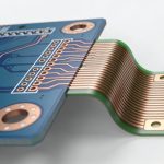
While Surface Mount Technology (SMT) dominates the world of ultra-compact consumer electronics, Through-Hole Technology (THT) remains the undisputed champion for rugged, high-stress, and high-power applications.
From aerospace systems to industrial power supplies and heavy-duty automotive connectors, components that must withstand intense physical stress, thermal cycling, or high currents rely heavily on THT.
At HanSphere, we offer advanced, semi-automated, and manual THT lines that run seamlessly alongside our high-speed SMT infrastructure, ensuring your hybrid boards receive the best of both worlds.
1. What is THT Assembly?
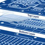
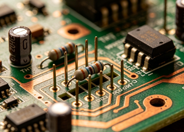
Through-Hole Technology involves inserting electronic components with wire leads into pre-drilled holes on a printed circuit board (PCB). These leads are then soldered to pads on the opposite side of the board.
The primary advantage of THT is the strong physical bond it creates. Because the component’s leads pass directly through the board, the solder joint can withstand far more mechanical pulling, twisting, and environmental vibration than an SMT joint resting purely on the surface.
2. The Step-by-Step THT Process at HanSphere
Step 1: Component Lead Prep & Forming
Electronic components often arrive with straight, long leads. Before insertion, these leads must be cut and bent (formed) to precisely match the hole spacing on the PCB. HanSphere uses automated forming machines to ensure uniform bending, preventing mechanical stress on the component body.
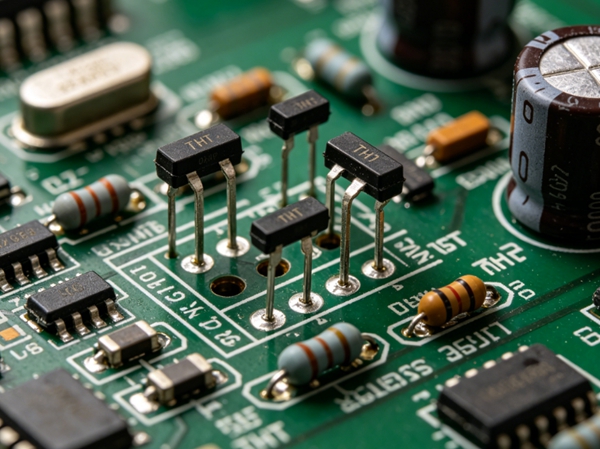
Step 2: Component Insertion (Manual or Automated)
Depending on the production volume and complexity, components are placed onto the board.
- Automated Insertion: Used for standard radial and axial components in high-volume runs.
- Manual Insertion: For complex, odd-form components like heavy transformers, terminal blocks, and specialized connectors, our highly skilled technician team places the parts by hand using strict ESD-safe protocols.
Step 3: Wave Soldering or Selective Soldering
Once the components are populated, the board moves to the soldering phase:
- Wave Soldering: The entire board passes over a wave of molten solder. The solder wicks up into the plated through-holes via capillary action, forming a perfect fillet.
- Selective Soldering: If the board already has SMT components on the bottom side that cannot be exposed to a full molten wave, we use a precision selective soldering machine to target individual through-hole pins without disturbing nearby surface-mount parts.
Step 4: Post-Soldering Inspection & Cleaning
Every THT joint undergoes rigid quality checks. Our team utilizes automated optical systems and manual visual inspection to ensure 100% solder barrel fill (IPC Class 2 or Class 3 compliance). Boards are then cleaned to remove active flux residues.
3. Design for Manufacturing (DFM) Rules for THT
To optimize your through-hole design for the HanSphere factory floor and keep production costs low, incorporate these rules into your CAD layout:
| Feature | Recommended Specification | Why It Matters |
| Hole-to-Lead Clearance | Component Lead Diameter + 0.2mm to 0.4mm | Too tight makes insertion impossible; too loose causes poor capillary solder fill. |
| Annular Ring Width | Minimum 0.5mm (20 mil) | Ensures enough copper pad area for a structurally sound solder joint. |
| Component Pitch | Match standard grid intervals (e.g., 2.54mm) | Allows for standard automated forming and insertion tools. |
| Thermal Relief Pads | Required on ground/power planes | Prevents the copper planes from acting as heat sinks, which causes cold solder joints. |
4. THT vs. SMT: Finding the Right Balance
Most modern electronics do not choose between one or the other; they use Mixed Assembly (Hybrid Boards).
- Use SMT for microcontrollers, memory, chip resistors, and high-speed digital loops.
- Use THT for input/output connectors, switches, electrolytic capacitors, and power stage components.
Internal Link: If you are unsure which technology fits your project budget, consult our SMT vs. THT Comparison Guide.
FAQ: THT Assembly Insights
A: THT requires more manual handling, lead forming, and secondary soldering steps (like selective soldering). However, designing the board with clear spacing and automated tool compatibility can drastically reduce these factory labor costs.
A: We manufacture strictly to IPC-A-610 Class 2 for standard industrial/commercial electronics, and can support Class 3 (High Reliability/Aerospace) upon explicit customer request.
A: Yes, the majority of our PCBA projects are hybrid. We typically run SMT reflow first, followed by through-hole wave or selective soldering.