Metal Core PCB
(MCPCB / Aluminum)
Aluminum-base and copper-base metal core boards engineered to move heat away from the junction — where standard FR4 thermal resistance becomes the limiting factor in your design.
A heat-spreading substrate — not just a circuit board
A metal core PCB replaces the standard FR4 core with a solid aluminum or copper base plate, bonded to the copper circuit layer through a thermally conductive dielectric layer. Heat generated at the component junction conducts vertically through this dielectric into the metal base, where it spreads laterally to a heatsink or chassis.
The dielectric layer is the critical engineering variable. Standard FR4 has a thermal conductivity around 0.3 W/m·K; MCPCB dielectrics range from 1.0 W/m·K for cost-sensitive designs up to 3.0 W/m·K for standard high-power LED work, and up to 8.0 W/m·K for ceramic-filled dielectrics used in the most thermally demanding power modules.
Base metal choice matters too. Aluminum 5052 and 6061 dominate LED and general power applications on cost and machinability; copper base is specified where maximum thermal spreading or higher mechanical strength is required, at a thermal-performance and cost premium.
Get MCPCB Quote →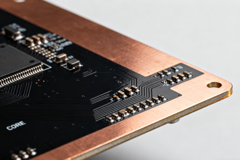
Three specification decisions that determine MCPCB thermal performance
The datasheet thermal conductivity number is only the starting point — the full construction determines what actually reaches the heatsink.
Dielectric Layer Thickness Is a Trade-off Between Isolation and Thermal Path
The dielectric layer sits between the copper circuit and the metal base, providing electrical isolation while conducting heat vertically. Thinner dielectric (75 µm) reduces thermal resistance but limits breakdown voltage; thicker dielectric (150 µm) raises breakdown voltage margin but increases thermal resistance. We specify dielectric thickness against your required breakdown voltage and junction temperature target — not a single default.
75–150 µm dielectric · 1.0–8.0 W/m·K · IPC-2S1B constructionsBase Metal Selection: Aluminum vs. Copper
Aluminum 5052-H32 and 6061-T6 offer good thermal spreading, low cost and easy CNC routing for standard LED and power supply boards. Copper base delivers roughly 2x the thermal conductivity of aluminum for the same thickness, and is specified for high-power modules where lateral heat spreading to the board edge is the bottleneck, not just vertical conduction through the dielectric.
Al 5052/6061 · Cu base · 0.8–3.2mm thickness · thermal spreadingBreakdown Voltage Rating Sets the Safety Margin
Per IPC standard test methods, breakdown voltage of the dielectric layer typically ranges 3kV to 4.5kV depending on thickness and filler composition. For LED drivers and power supplies operating from mains-derived rails, breakdown voltage rating must be reviewed against creepage and clearance requirements — a board that meets UL 796 recognition on the dielectric material alone is not automatically safety-compliant at the finished-board level.
UL 796 recognized · 3–4.5kV breakdown · dielectric withstand testFull metal core PCB fabrication specification
All dielectric and thermal data verified against supplier datasheets and confirmed by dielectric withstand test on every production lot.
Fabrication Parameters
| Base Metal | Aluminum 5052 / 6061 · Copper |
| Base Thickness | 0.8 mm – 3.2 mm |
| Dielectric Thickness | 75 µm – 150 µm |
| Copper Weight | 1 oz – 10 oz |
| Construction | Single-layer · Double-layer · Multilayer MCPCB |
Performance & Standards
| Dielectric Thermal Conductivity | 1.0 – 3.0 W/m·K standard · up to 8.0 W/m·K advanced |
| Breakdown Voltage | 3kV – 4.5kV |
| Surface Finish | HASL-lead-free · ENIG · OSP · White/Black Solder Mask |
| Safety Recognition | UL 796 dielectric recognized |
| Prototype Turnaround | 72h express · 6 days standard |
How metal core PCB is manufactured
A bonding-critical process — the dielectric-to-metal interface determines thermal and mechanical reliability for the life of the board.
Base Plate Prep & Circuit Imaging
Aluminum or copper base plate is surface-treated and the copper foil is laminated with the thermally conductive dielectric, then photolithographically imaged to the circuit pattern.
Etch & Dielectric Bond
Copper is etched to the final circuit and hot-pressed onto the metal base through the dielectric layer under controlled heat and pressure to eliminate voids at the thermal interface.
CNC Routing & Drilling
Mechanical outline routing and hole drilling are performed with carbide tooling matched to the metal base hardness, avoiding delamination at the dielectric edge.
Solder Mask, Finish & Dielectric Test
Solder mask, surface finish and legend are applied, followed by 100% dielectric withstand voltage test to confirm breakdown voltage rating before shipment.
Where metal core PCB is the right choice
Any design where the failure mode is thermal, not electrical, is a candidate for metal core construction.
LED Street & Area Lighting
Aluminum-base single-layer MCPCB for high-power LED fixtures operating outdoors at sustained high ambient temperature.
Automotive Lighting
Headlamp and DRL modules with high-CCT LEDs requiring stable junction temperature across the automotive range.
Power Supplies & Converters
MCPCB for switching regulator and AC/DC converter boards where power MOSFETs need direct thermal path to chassis.
Motor Drives
Copper-base MCPCB for motor driver stages dissipating continuous switching losses in compact enclosures.
Class D Audio Amplifiers
Aluminum-base boards for output stage MOSFETs in Class D amplifier modules requiring low thermal resistance.
Heat-Sensitive Automotive Electronics
Under-hood and near-engine electronic modules where component derating margin depends on effective heat spreading.
Industrial Power Modules
Multilayer MCPCB for IGBT and power module carriers in industrial drives and renewable energy inverters.
Solar & UV Curing Arrays
High-density LED arrays for UV curing and horticultural lighting requiring uniform thermal distribution across the panel.
MCPCB quality — from dielectric selection to breakdown voltage test.
Quality on a metal core board starts with dielectric material qualification. Our DFM review checks thermal path calculations against your power dissipation figures. Post-fab, 100% dielectric withstand test confirms breakdown voltage on every board.
- ISO 9001 : 2015Third-party audited quality management
- IPC-6012Rigid PCB qualification & performance
- IPC-A-600 Class 2 / 3Acceptability criteria
- UL 796Dielectric material safety recognition
- RoHS / REACHEU hazardous substance compliance
Inspection & Testing Methods
- 100% Electrical Test — Flying Probe / FixtureOpen / short on all nets
- 100% Dielectric Withstand Voltage TestConfirms 3kV–4.5kV breakdown rating per lot
- Thermal Resistance VerificationMeasured against dielectric datasheet W/m·K value
- 100% AOI — Circuit LayerAutomated optical inspection
- Peel Strength — Copper to DielectricBond integrity per IPC-TM-650 2.4.8
- Solder Mask Adhesion & ThicknessCross-hatch and thickness gauge test
- Thermal Shock Cycling-40°C to +125°C on request
- Dimensional / CNC Outline VerificationPost-routing measurement against drawing
Metal core boards we have built
Real thermal management challenges — solved.
200W LED Street Light Thermal Redesign
Migrated from 1.0 W/m·K dielectric aluminum board to 3.0 W/m·K construction after field reports of premature LED lumen depreciation in high-ambient regions.
Junction temperature reduced by 18°C at rated drive current. L70 lumen maintenance life projection improved from 35,000h to 60,000h.
500W AC/DC Converter Copper-Base MCPCB
Double-layer copper-base MCPCB replacing a heatsink-mounted FR4 daughtercard, integrating the thermal path directly into the power stage board.
Eliminated separate heatsink assembly, reducing enclosure volume by 22% while holding MOSFET case temperature within derating spec at full load.
Automotive DRL Module Aluminum MCPCB
1.2mm aluminum-base single-layer board for daytime running light module, qualified across -40°C to +105°C automotive ambient range.
Passed 500-cycle thermal shock qualification with zero delamination at the dielectric-to-copper interface. In production for 2 years.
Common questions about Metal Core PCB
Technical questions about MCPCB thermal design, materials and manufacturing.
For general LED lighting and moderate power applications, 1.0–2.0 W/m·K dielectric is typically sufficient and cost-effective. For high-power LED (street lighting, high-bay), power converters and motor drives, 3.0 W/m·K is the common standard. For the most thermally demanding power module and high-density LED array designs, ceramic-filled dielectrics up to 8.0 W/m·K are available. We recommend a thermal review of your power dissipation and target junction temperature before finalizing dielectric selection.
Aluminum 5052 or 6061 is the default choice for most LED and general power applications — good thermal spreading, lower cost, and easier CNC routing. Copper base delivers roughly double the thermal conductivity of aluminum at equivalent thickness and is worth the cost premium when lateral heat spreading across the board (not just vertical conduction through the dielectric) is the limiting factor, such as in high-power modules with concentrated heat sources.
Yes. Single-layer MCPCB (one circuit layer on the metal base) is the most common and lowest-cost construction, used for the majority of LED applications. Double-layer and multilayer MCPCB constructions place additional circuit layers above the base, connected by plated through-holes or vias, and are used where the design needs more routing density than a single layer can support, such as driver circuitry integrated onto the same board as the LED array.
Standard MCPCB dielectric breakdown voltage ranges from 3kV to 4.5kV depending on thickness and filler composition. For boards handling mains-derived voltage, breakdown voltage rating should be reviewed alongside creepage and clearance distances required by your end-product safety standard (e.g., IEC 62368-1). We recommend sharing your safety certification target with our engineering team during the DFM review so dielectric thickness and voltage rating are matched correctly.
We support copper weights from 1 oz up to 10 oz on MCPCB circuit layers. Heavier copper (4 oz and above) is common in power supply and motor drive MCPCB designs to increase current-carrying capacity of the traces alongside the thermal path through the dielectric. Heavier copper requires wider minimum trace/space due to etch factor — this is reviewed during DFM.
Yes. 100% of MCPCB production is tested for dielectric withstand voltage before shipment, confirming the board meets the specified breakdown voltage rating (3kV–4.5kV depending on construction). Test results are included in the quality documentation package supplied with each order, alongside the material Certificate of Compliance for the dielectric layer.
Get your MCPCB thermal design reviewed — today.
Send your Gerber, power dissipation figures and target junction temperature. Our engineers review dielectric selection, base metal and breakdown voltage within 8 hours.
- DFM & thermal review included with every enquiry
- NDA signed on request — standard practice
- Response within 8 working hours
- 72-hour express prototype available
- No commitment required to get a quote
Request a Quote
Fill in the details below and we'll get back to you shortly.