As signal speeds continue to increase, PCB material selection becomes more than a mechanical decision. Electrical properties that had little impact on low-speed circuits can become critical in high-speed digital and RF designs.
One of those properties is dielectric loss, often shown on material datasheets as Df or dissipation factor.
Although Df is usually discussed together with dielectric constant (Dk), it describes a different characteristic of the material. Understanding the difference helps engineers choose laminates that match both performance requirements and manufacturing budgets.
What Is Dielectric Loss?
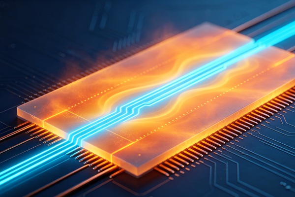
Dielectric loss describes the amount of signal energy that is absorbed by the insulating material as an electrical signal passes through it.
Instead of all the energy being transmitted along the copper traces, a small portion is converted into heat inside the dielectric material.
The lower the dielectric loss, the more efficiently the PCB transmits high-frequency signals.
If you’re new to material parameters, it’s helpful to first understand PCB Dielectric Constant (Dk) Explained for Material Selection, since Dk and Df are usually evaluated together.
What Is Dissipation Factor (Df)?
Dissipation factor is the numerical value used to describe dielectric loss.
Material suppliers list Df in laminate datasheets so designers can compare electrical performance between different materials.
In general:
- Lower Df means lower signal loss.
- Higher Df means more energy is lost as heat.
For low-speed electronics, these differences may have little practical impact. As frequencies increase, however, Df becomes a more important part of material selection.
Why Dielectric Loss Matters
Not every PCB requires an ultra-low-loss material, but there are applications where Df has a noticeable influence.
High-Speed Digital Systems
Interfaces operating at very high data rates are more sensitive to signal attenuation.
Lower-loss materials help preserve signal quality over longer transmission paths.
RF and Microwave Circuits
RF signals travel at much higher frequencies than conventional digital circuits.
Materials with a low Df reduce insertion loss and improve overall system efficiency.
If you’re comparing common laminate options, FR4 vs Rogers PCB for High-Frequency Design explains why specialized materials are often selected for RF products.
Long Transmission Paths
Signal loss increases as trace length increases.
For backplanes, communication equipment, and networking hardware, dielectric loss becomes increasingly important.

Typical Df Values of Common PCB Materials
Different laminate systems provide different levels of dielectric loss.
| Material | Typical Df Range |
|---|---|
| Standard FR4 | 0.015–0.025 |
| High-Tg FR4 | 0.012–0.020 |
| Low-Loss FR4 | 0.005–0.010 |
| Rogers Materials | 0.002–0.004 |
| PTFE-Based Materials | Below 0.002 |
Actual values vary depending on the laminate manufacturer and test frequency.
Df Is Not the Same as Dk
Although Dk and Df often appear together on material datasheets, they describe different characteristics.
| Property | Dk | Df |
|---|---|---|
| Main purpose | Signal propagation | Signal energy loss |
| Primary influence | Impedance and delay | Signal attenuation |
| Importance | All PCB designs | High-speed and RF designs |
When selecting materials for demanding applications, both values should be reviewed together rather than independently.
Factors That Affect Dielectric Loss
Several variables influence the measured Df of a PCB material.
Material Composition
Different resin systems naturally produce different dielectric losses.
This is one reason why standard FR4 and high-frequency laminates perform differently.
Operating Frequency
Dielectric loss generally becomes more significant as signal frequency increases.
A material that performs well at lower frequencies may not provide the same performance at microwave frequencies.
Temperature
Electrical properties can change slightly as operating temperature changes.
For products used in demanding environments, this should be considered during material selection.
Manufacturing Quality
Consistent laminate production helps maintain stable electrical performance between production batches.
The article PCB Laminate Explained for PCB Design and Manufacturing discusses how laminate construction contributes to PCB quality.
When Is a Low-Df Material Necessary?
Low-loss materials are commonly selected for:
- RF communication equipment
- Microwave systems
- Radar electronics
- High-speed networking hardware
- Data center equipment
- High-frequency test equipment
For many industrial control products, consumer electronics, and general-purpose PCBs, standard FR4 continues to provide suitable performance.
Choosing a premium laminate only makes sense when the application requires it.
Material Selection Should Balance Performance and Cost
Lower Df materials generally cost more than conventional FR4.
For many commercial products, the additional expense offers little practical benefit.
The better approach is to match the material to the electrical requirements of the design instead of selecting the lowest Df available.
Understanding the differences between available materials is an important part of PCB design. The overview in PCB Material Types Used in Modern Printed Circuit Boards is a useful starting point when comparing substrate options.
How to Select PCB Materials Based on Df
- Step 1
Determine the operating frequency and data rate of the circuit.
- Step 2
Estimate acceptable signal loss across the longest transmission paths.
- Step 3
Compare Df together with Dk, thermal properties, and manufacturing requirements.
- Step 4
Review the selected laminate with your PCB manufacturer before finalizing the stackup.
Conclusion
Dielectric loss is one of the key electrical properties used to evaluate PCB materials.
For conventional electronic products, standard FR4 usually provides sufficient performance. As frequencies increase, however, lower-loss materials can help reduce attenuation and maintain signal quality.
Rather than focusing on Df alone, engineers should evaluate dielectric loss together with dielectric constant, thermal performance, manufacturability, and overall project cost to select the most suitable PCB material.
Frequently Asked Questions
A:Dielectric loss is the electrical energy absorbed by the insulating material as signals travel through a printed circuit board.
A:Df, or dissipation factor, is the value used to describe dielectric loss. Lower Df values indicate lower signal loss.
A:Not necessarily. Low-Df materials are beneficial for high-speed and RF applications, but many standard electronic products perform well with conventional FR4.
A:High-frequency laminates such as Rogers materials and PTFE-based materials generally provide lower dielectric loss than standard FR4.
A:Both properties describe the electrical behavior of PCB materials. Dk influences signal propagation, while Df indicates how much signal energy is lost during transmission.