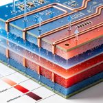
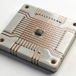
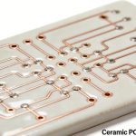
When designing a PCB, material selection is not only about thickness, temperature resistance, or cost.
For high-speed and high-frequency circuits, the electrical properties of the material become equally important.
One of the most important parameters is dielectric constant (Dk).
Dk affects how electrical signals travel through the PCB. It influences impedance, propagation delay, signal integrity, and overall circuit performance.
For simple low-speed boards, Dk may not receive much attention. However, as signal frequencies increase, choosing the right dielectric material becomes increasingly important.
What Is PCB Dielectric Constant?
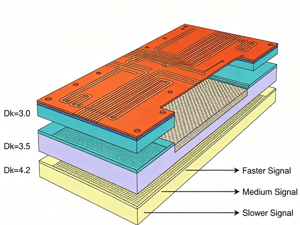
The dielectric constant, commonly written as Dk, describes how effectively a material stores electrical energy compared with air.
In PCB design, Dk represents the electrical behavior of the insulating material between copper layers.
A material with a higher Dk slows down electrical signals more than a material with a lower Dk.
Different PCB materials have different dielectric constants because of differences in resin systems, fiberglass structure, and manufacturing processes.
Related reading:
Why Dk Matters in PCB Design
Dk affects several important PCB characteristics.
Impedance Control
Controlled impedance is critical in high-speed digital and RF circuits.
The dielectric constant affects the relationship between:
- Trace width
- Copper thickness
- Dielectric thickness
- Signal layer structure
A change in Dk can alter impedance values and create signal integrity issues.
Signal Speed
Electrical signals travel slower through materials with higher dielectric constants.
This affects:
- Propagation delay
- Timing performance
- High-speed communication signals
For applications such as networking equipment, servers, and advanced communication systems, material selection becomes more important.
Signal Integrity
Incorrect dielectric properties can contribute to:
- Signal reflection
- Crosstalk
- Timing errors
- Increased loss
For high-speed designs, engineers often consider Dk together with dielectric loss (Df).
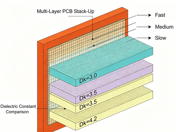
Typical Dk Values of Common PCB Materials
Different materials have different dielectric characteristics.
| Material | Typical Dk Range |
|---|---|
| Standard FR4 | Around 4.0–4.8 |
| High-Tg FR4 | Around 4.0–4.5 |
| Rogers High-Frequency Materials | Around 2–3.5 |
| PTFE-Based Materials | Around 2–3 |
Actual values depend on frequency, resin content, glass style, and manufacturer specifications.
Why FR4 Dk Is Not a Fixed Number
Many people assume FR4 always has one specific Dk value.
In reality, FR4 is a material family rather than a single material.
Its Dk can vary depending on:
- Resin content
- Fiberglass weave style
- Test frequency
- Laminate manufacturer
For this reason, engineers should always use the manufacturer’s datasheet values when designing controlled impedance circuits.
Related reading:
Dk and High-Frequency PCB Materials
At higher frequencies, small differences in dielectric properties can affect performance.
Materials designed for RF and microwave applications usually provide:
- More stable Dk values
- Lower dielectric loss
- Better signal consistency
This is why materials such as Rogers and PTFE are often selected instead of standard FR4 for demanding RF applications.
Related reading:
- FR4 vs Rogers PCB for High-Frequency Design
- Low-Loss PCB Materials for RF and Microwave Circuits
Dk vs Df
Dk and Df are related but represent different material properties.
Dk (Dielectric Constant)
Mainly affects:
- Signal propagation speed
- Impedance calculation
- Electrical length
Df (Dissipation Factor)
Mainly affects:
- Signal loss
- Heat generated by dielectric loss
- High-frequency efficiency
For high-frequency PCB design, both values need to be considered together.
Factors That Influence PCB Dielectric Constant
The Dk value of a PCB material depends on several factors.
Resin Content
Higher resin content generally changes the dielectric behavior of the laminate.
Fiberglass Structure
Different glass weave styles can create local variations in Dk.
Operating Frequency
Dk values may change depending on the measurement frequency.
A material specification at low frequency may not represent actual high-speed performance.
Manufacturing Process
Lamination conditions and material consistency can influence final electrical characteristics.
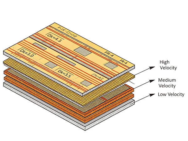
How to Select PCB Materials Based on Dk
- Step 1
Identify the operating frequency and signal speed requirements.
- Step 2
Determine whether standard FR4 performance is sufficient.
- Step 3
Compare Dk, Df, thermal properties, and cost together.
- Step 4
Confirm the selected laminate with your PCB manufacturer before stackup design.
Common Mistakes When Using Dk Data
Using a Generic FR4 Dk Value
A common mistake is using a general Dk number found online instead of the actual laminate datasheet.
Different FR4 materials can have different electrical properties.
Ignoring Frequency Effects
Dk values can change with frequency, especially in high-speed applications.
Selecting Material Only by Cost
The cheapest material may not provide the required signal performance.
Material selection should consider the complete product requirement.
Conclusion
PCB dielectric constant is a key material parameter that affects signal behavior, impedance control, and high-frequency performance.
For standard electronics, common FR4 materials can meet most requirements. However, high-speed and RF applications often require materials with more stable dielectric characteristics.
Understanding Dk helps engineers select suitable PCB materials, improve signal integrity, and reduce design risks before manufacturing begins.
Frequently Asked Questions
A: PCB dielectric constant (Dk) describes the electrical property of the insulating material that affects how signals travel through the PCB.
A: Dk affects impedance, signal speed, propagation delay, and signal integrity, especially in high-speed and high-frequency circuits.
A: No. FR4 is a material category, and its Dk varies depending on resin content, fiberglass style, frequency, and manufacturer.
A: Not always. The appropriate Dk depends on the application, impedance requirements, signal speed, and circuit design.
A: High-frequency materials such as Rogers and PTFE-based laminates are commonly used when lower and more stable dielectric properties are required.