When engineers specify a PCB, they usually start with the layer count and board thickness.
Copper thickness deserves the same level of attention.
It influences far more than the amount of copper on the board. Current capacity, voltage drop, heat dissipation, trace width, and manufacturing cost are all affected by this single parameter.
For most commercial products, 1 oz copper is the standard choice. However, that does not mean it is always the best option.
Selecting the appropriate copper thickness should always be based on the electrical and thermal requirements of the design.
What PCB Copper Thickness Means
Copper thickness refers to the thickness of the conductive copper foil laminated onto the PCB substrate.
In the PCB industry, copper thickness is commonly expressed as ounces per square foot (oz/ft²) instead of millimeters or micrometers.
The conversion is approximately:
| Copper Weight | Approximate Thickness |
|---|---|
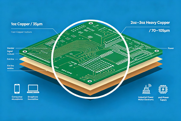
| 0.5 oz | 17 μm |
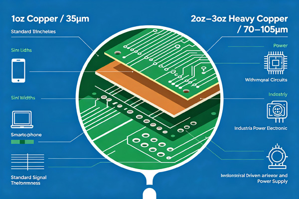
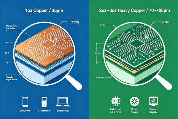
| 1 oz | 35 μm |
| 2 oz | 70 μm |
| 3 oz | 105 μm |
| 4 oz | 140 μm |
These values represent the finished copper thickness before additional plating during fabrication.
Why Copper Thickness Matters
Copper thickness affects several aspects of PCB performance.
A thicker copper layer can:
- carry higher current
- reduce resistive losses
- improve heat spreading
- increase mechanical robustness
At the same time, it may require wider spacing, larger trace widths, and additional manufacturing controls.
Choosing thicker copper simply because it appears “better” is rarely the most economical solution.
Common Copper Thickness Options
0.5 oz Copper
Half-ounce copper is often selected for designs with:
- high routing density
- fine-pitch components
- low-current signals
The thinner copper allows finer trace geometry, making it useful for compact digital products.
1 oz Copper
One-ounce copper is the industry standard.
It provides a good balance between electrical performance, manufacturability, and cost.
Typical applications include:
- consumer electronics
- communication equipment
- industrial control boards
- general-purpose embedded systems
Most PCB manufacturers treat 1 oz copper as the default specification unless another value is requested.
2 oz Copper
Two-ounce copper is commonly used where additional current capacity is required.
Typical applications include:
- motor controllers
- industrial power supplies
- LED drivers
- battery management systems
Compared with 1 oz copper, traces can carry higher current without increasing temperature as quickly.
However, routing density may decrease because wider spacing is often required.
3 oz Copper and Above
Copper weights above 2 oz are generally classified as heavy copper.
These boards are designed for demanding electrical environments, such as:
- power conversion equipment
- welding systems
- renewable energy products
- high-current industrial controls
Manufacturing heavy copper PCBs requires tighter process control than standard boards.
How Copper Thickness Affects PCB Design
Copper thickness should be considered early in the layout process.
Changing it after routing has been completed often requires design adjustments.
Current Carrying Capacity
Thicker copper reduces electrical resistance, allowing traces to carry more current.
In many cases, increasing copper weight can reduce the need for excessively wide traces.
Heat Dissipation
Copper also helps distribute heat across the PCB.
Although FR4 is not a highly conductive material, thicker copper can improve heat spreading and reduce localized hot spots.
Trace Width
Current capacity depends on both copper thickness and trace width.
Designers often balance these two factors to meet available board space.
Manufacturing Cost
Increasing copper weight generally increases fabrication cost.
Additional processing steps and tighter manufacturing tolerances may be required, particularly for multilayer boards.
Related reading: Multilayer PCB Design Guide
Selecting Copper Thickness for Different Applications
Different products have different requirements.
Consumer Electronics
Most products perform well with:
- 1 oz copper
This provides sufficient performance while keeping manufacturing costs under control.
Industrial Equipment
Industrial systems frequently use:
- 2 oz copper
The additional copper improves current handling and thermal performance.
Power Electronics
High-current circuits often require:
- 2 oz or heavier copper
The exact specification depends on operating current, available board space, and cooling strategy.
High-Speed Digital Designs
High-speed PCBs do not automatically require thicker copper.
Instead, designers should focus on:
- controlled impedance
- stackup planning
- return path continuity
Related reading:
How to Choose the Right Copper Thickness
Step 1
Calculate the maximum current carried by each trace.
Step 2
Estimate acceptable temperature rise.
Step 3
Determine available routing space.
If board space is limited, increasing copper thickness may reduce the required trace width.
Step 4
Review manufacturing capabilities with your PCB supplier before finalizing the design.
Not every PCB requires heavy copper processing.
Common Mistakes When Specifying Copper Thickness
Several issues appear regularly during PCB reviews.
One common mistake is specifying heavy copper for the entire board when only a few power traces require it.
Another is assuming thicker copper automatically improves every design.
For high-speed digital circuits, signal integrity depends more on stackup, routing, and impedance control than on copper weight alone.
Copper thickness should always match the electrical requirements of the product.
Conclusion
Copper thickness plays an important role in PCB performance, but there is no universal specification that fits every application.
For many commercial products, 1 oz copper remains the most practical choice. Higher copper weights become valuable when current capacity, thermal performance, or mechanical durability are more demanding.
Selecting the appropriate copper thickness early in the design process helps improve manufacturability, control cost, and achieve reliable long-term performance.
How to Select Copper Thickness
- Step 1
Determine the maximum operating current for each power path.
- Step 2
Evaluate thermal requirements and allowable temperature rise.
- Step 3
Balance trace width, available routing space, and layer count.
- Step 4
Confirm the copper specification with your PCB manufacturer before releasing production files.
Frequently Asked Questions
A: Most FR4 PCBs are manufactured with 1 oz (35 μm) copper as the standard option.
A: No. While 2 oz copper carries more current, it also increases manufacturing cost and may reduce routing density.
A: Not necessarily. Signal integrity is more closely related to stackup design, impedance control, and return paths than copper thickness alone.
A: Heavy copper is commonly used in high-current applications such as power supplies, motor drives, renewable energy equipment, and industrial control systems.
A: Yes. Heavier copper typically requires additional fabrication processes and tighter manufacturing control, which increases production cost.