Almost every electronic product contains a PCB board.
Phones.
Industrial equipment.
Medical devices.
Cars.
If electronics need components to communicate reliably, there is usually a PCB underneath.
But despite how common they are, many people still ask:
What exactly is a PCB board?
The short answer:
A PCB board provides electrical connections and mechanical support for electronic components.
The real answer is a bit more interesting.
What Is a PCB Board?
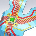
A PCB (Printed Circuit Board) is a board that connects electronic components using conductive copper traces.
Instead of wires connecting every component manually, the PCB routes signals through precisely designed copper pathways.
A PCB typically includes:
- copper traces
- substrate material
- solder mask
- silkscreen markings
- drilled vias
Together, these layers create an organized electrical system.
How Does a PCB Board Work?
Electronic components are mounted onto the PCB.
Copper traces then carry:
- signals
- power
- ground connections
The PCB acts like:
the “road system” of electronics.
Without these connections:
- chips cannot communicate
- sensors cannot transfer data
- power cannot be distributed
Good PCB design ensures signals move reliably and efficiently.
Main Parts of a PCB Board
Substrate Material
The substrate forms the physical base.
Most common material:
- FR4
For high-frequency or thermal applications:
- Rogers materials
- ceramic substrates
Related:
- FR4 vs High-Tg FR4: What’s the Difference
- FR4 vs Rogers PCB for High-Frequency Design
- Ceramic PCB vs FR4 PCB
Copper Layer
Copper forms electrical pathways.
Functions:
- signal routing
- power delivery
- grounding
Copper thickness affects:
- current capacity
- impedance
- heat dissipation
Solder Mask
Usually green (but not always).
Purpose:
- prevent solder bridges
- protect copper
- improve reliability
Silkscreen
Printed labels help identify:
- components
- polarity
- connectors
- reference designators
Vias
Vias connect layers electrically.
Common types:
- through-hole vias
- blind vias
- buried vias
Related: PCB Via Design in High-Speed Circuits

Types of PCB Boards
PCB boards come in many forms.
Single-Sided PCB
One copper layer.
Common for:
- simple electronics
- low-cost products
Double-Sided PCB
Copper on both sides.
Allows:
- more routing flexibility
Widely used in consumer electronics.
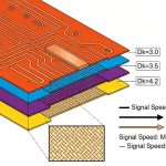
Multilayer PCB
Multiple copper layers stacked together.
Common examples:
- 4-layer
- 6-layer
- 8-layer
- 10-layer boards
Used in:
- computers
- telecom
- industrial systems
Related: High-Speed PCB Stackup Design
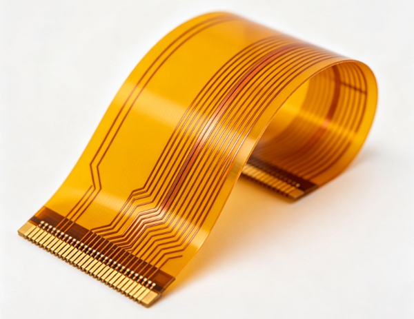
Flexible PCB
Made with bendable substrate materials.
Advantages:
- lightweight
- space saving
Common in:
- wearables
- compact devices
Rigid-Flex PCB
Combines:
- rigid PCB sections
- flexible interconnects
Often used where reliability matters.
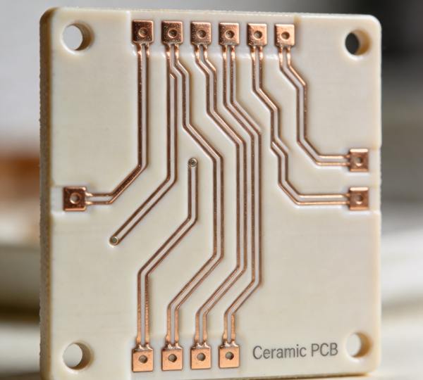
Ceramic PCB
Designed for:
- thermal management
- power electronics
- RF systems
Related: Ceramic PCB Applications in Power Electronics, LED, and RF Systems
Common PCB Materials
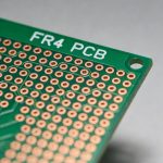
FR4 PCB
Most widely used.
Good balance of:
- cost
- performance
- manufacturability
High-Tg FR4
Improved heat resistance.
Better for:
- higher temperatures
- lead-free assembly
Rogers Materials
Used in:
- RF
- microwave applications
Offers:
- lower dielectric loss
Ceramic Materials
Excellent:
- thermal conductivity
- dimensional stability
PCB Manufacturing Process
A simplified process looks like this:
1. PCB Design
Engineers create:
- schematic
- layout
- Gerber files
2. Fabrication
Board manufacturing includes:
- imaging
- etching
- drilling
- plating
- lamination
3. PCB Assembly
Components are installed through:
- SMT assembly
- through-hole assembly
Related: PCB Assembly Process Explained
4. Testing and Inspection
Common methods:
- AOI
- X-ray
- ICT
- flying probe
- functional testing
Related:
Key PCB Design Considerations
Modern PCBs must consider:
Signal Integrity
High-speed signals require:
- impedance control
- proper routing
Related: Controlled Impedance PCB Design
Power Integrity
Stable power delivery matters.
Related: PCB Power Integrity Design
Thermal Management
Heat affects reliability.
Manufacturability
Good DFM reduces production issues.
Related: High-Speed PCB Design for Manufacturing & Yield
How to Choose the Right PCB Board
Consider:
Application
Consumer, RF, automotive, industrial?
Electrical Requirements
Speed, current, frequency?
Thermal Performance
Will the board generate heat?
Reliability Requirements
Harsh environment?
Related: PCB Reliability Testing
Budget
Performance must match cost.
Common PCB Problems
Typical issues include:
- signal interference
- poor solder quality
- thermal failure
- impedance mismatch
- manufacturing defects
Many problems can be prevented through proper design review.
Related: PCB Design Review Checklist
Conclusion
PCB boards are the foundation of modern electronics.
They provide the electrical and mechanical platform that allows components to function reliably. From simple single-sided boards to complex multilayer high-speed designs, choosing the right PCB type, material, and manufacturing process is essential for performance and reliability.
FAQ
A: PCB stands for Printed Circuit Board, used to electrically connect components.
A: FR4 is the most commonly used PCB substrate material.
A: Rigid PCBs do not bend, while flexible PCBs are designed to flex.
A: PCB boards can range from 1 layer to more than 20 layers depending on complexity.
A: Testing helps ensure quality, functionality, and long-term reliability.